OpenGL 101: Drawing primitives - points, lines and triangles
Posted on May 13, 2013 by Paul
The code for this post is on GitHub: https://github.com/sol-prog/OpenGL-101.
This is the second article from my OpenGL 101 series. In the first article we’ve seen how to open a window for our OpenGL application with the GLFW library and how to compile and run the code on Windows, OS X and Linux. It is time to actually draw something using OpenGL.
First, let me mention that OpenGL is a low level API, this means that it has no support for drawing complex geometrical objects. It is the programmer’s job to combine the geometrical primitives from OpenGL in complex shapes and bodies. The basic geometrical primitives that the core OpenGL profile provide to us are points, lines and triangles.
For simplicity, we are going to use only two dimensional drawings in this article, but keep in mind that OpenGL allows us to represent three dimensional objects, more on this in a future article. For now, let’s try to draw the four triangles from the next figure:
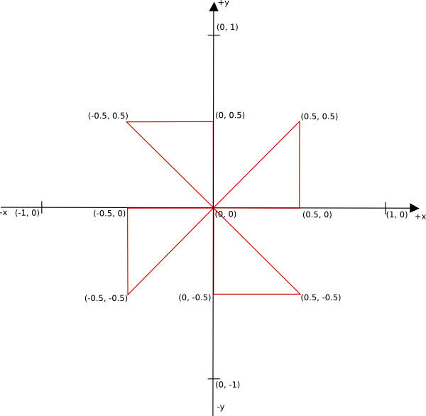
From a geometrical point of view, a triangle is completely defined by the position in space of his three corners or vertices. In OpenGL terminology, a vertex can be seen as a collection of attributes like position, color, texture coordinates etc …
In the above figure we have four triangles and twelve vertices. Each vertex from our figure has a position attribute, let’s ignore for the moment any other possible attribute like a color. We can store these vertices in a C++ array:
 1 	GLfloat vertices_position[24] = {
 2 		0.0, 0.0,
 3 		0.5, 0.0,
 4 		0.5, 0.5,
 5
 6 		0.0, 0.0,
 7 		0.0, 0.5,
 8 		-0.5, 0.5,
 9
10 		0.0, 0.0,
11 		-0.5, 0.0,
12 		-0.5, -0.5,
13
14 		0.0, 0.0,
15 		0.0, -0.5,
16 		0.5, -0.5,
17 	};
If you look closely, you may notice that the points are written counterclockwise, this is important to keep in mind. By default, in OpenGL, a triangle with his vertices stored in counterclockwise order is said to be front facing. Why is this distinction important? We can instruct OpenGL to render only one of the two faces of a triangle surface (the front or the back); the default is to render both faces. Another observation about the above array is that it stores only the x, y coordinates for our triangles, this is because the z coordinate is zero for all twelve vertices.
So, how does OpenGL draws our triangles, now that we have their vertices in an array ? The first step is to transfer the content of the above array in a Vertex Buffer Object. A Vertex Buffer Object, or VBO, is a chunk of memory managed by OpenGL, basically it is a piece of the memory of your video card.
A VBO needs to be created, allocated and filled with data. We can also fill the VBO with data in the allocation step:
1 	// Create a Vector Buffer Object that will store the vertices on video memory
2 	GLuint vbo;
3 	glGenBuffers(1, &vbo);
4
5 	// Allocate space and upload the data from CPU to GPU
6 	glBindBuffer(GL_ARRAY_BUFFER, vbo);
7 	glBufferData(GL_ARRAY_BUFFER, sizeof(vertices_position), vertices_position, GL_STATIC_DRAW);
Line 3 from the above piece of code will create a handle for our VBO, using the glGenBuffers function. Keep in mind that this function can create an array of handles if needed; for our particular case we have a single VBO so one handle will suffice. Once a VBO is created, we need to bind it in order to modify or use it, this is what line 6 does with the glBindBuffer function. The last line will allocate space for the VBO and fill it with the content of our vertices_position array.
Once we have our data in a VBO, we can send it through the OpenGL pipeline - a number of steps and transformations through which our vertices will pass; the result is written in a framebuffer. The glfwSwapBuffers() function from GLFW will replace the current, visible framebuffer (the surface of our window), with the result of the rendering process. A simplified scheme of the OpenGL pipeline is presented in the next figure:
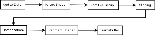
The above figure is a simplified model of the entire OpenGL pipeline, it doesn’t include any of the optional steps. From the point of view of a beginner, what is important in the above scheme are the vertex shader and the fragment shader. A shader is a, typically small, program that is executed on the video card. A shader is written in GLSL, the OpenGL Shading Language, a language similar with C.
A vertex shader is executed for every vertex in a VBO, his role is to, potentially, apply various transformations on the vertices position attribute and pass through other attributes like color, texture coordinates etc … It is the programmer’s responsibility to write a vertex shader for every OpenGL based application.
The next step, in our simplified model of the OpenGL pipeline, is the Primitive Setup stage that will organize the vertices into geometric primitives (points, lines and triangles) for the next two stages.
In the clipping stage, the primitives that lies outside of the viewing volume are split in smaller primitives. The default viewing volume in OpenGL is a cube, [-1, +1] x [-1, +1] x [-1, +1], with the origin in the middle of the current viewport (a rectangular area of our window, for our case the viewport has the same dimensions as our window), the positive x axis points to the right, the positive y axis points up and the positive z axis points toward the viewer. If, for example, one of our triangles corners will be outside of the viewing volume, say at -2.0, 0, the clipping stage will split this triangle in smaller triangles and remove the triangles that are outside of the viewing volume. This stage is executed by OpenGL.
In the rasterization stage, the primitives that exit the clipping stage are transformed into fragments. Which of these fragments will end as a pixel value in the final framebuffer is decided in the next stage of the pipeline. In the book recommended at the end of this article, it is suggested to think at these fragments as potential pixels.
The fragment shader, also the programmer’s responsibility, can potentially determine the fragment final color, discard some fragments, or use texture mapping.
After the fragment shader, the color of a fragment can potentially be further modified if the depth and stencil tests are enabled, or if blending was enabled.
From our simplified approach point of view, we are interested in the two mandatory shaders of any OpenGL core application, the vertex and the fragment shaders. In other words, we need to implement these two shaders if we want to draw something.
Let’s start with the implementation of a simple vertex shader:
1 #version 150
2
3 in vec4 position;
4
5 void main() {
6 	gl_Position = position;
7 }
The first line of the above shader specifies the shader language used, for OpenGL 3.2 the corresponding shader language version is 1.50. Next, we have a global variable of type vec4 that will receive the position of a vertex, a GLSL vector that can store 4 values, by default this is initialized with (0,0,0,1). A small note here, OpenGL represents internally any vertex position as a four value vector, we are going to talk more about this in a future article about Math in OpenGL :). From our point of view, if we send a two value x, y position to the shader, the last two numbers will remain with the default values of 0 and 1. Any shader needs a main function, like the one declared in line 5. Line 6 sets the value of an internal variable from GLSL, gl_position, to the value of our vertex position.
Next, we present a simple fragment shader:
1 #version 150
2
3 out vec4 out_color;
4
5 void main() {
6 	out_color = vec4(1.0, 1.0, 1.0, 1.0);
7 }
Line 3 of the fragment shader defines a global variable that will be used to set the color of every fragment to white, see line 6. As mentioned in the first article of this series, OpenGL uses internally a four dimensional color space, RGBA, in this space 1.0, 1.0, 1.0, 1.0 represents white opaque (no transparency).
For maximum flexibility, we are going to save the above two shaders in two separate files vert.shader and frag.shader. Some authors keep the shaders in C-style strings in their code, while this avoids the need to read the shader files from the disk it will also require the recompilation of the entire application for any small change in the shaders. The real problem with the shader code stored as string in the C++ code is that when you have an error in your shader code it could be a bit difficult to find the corresponding error line. Another disadvantage is that you don’t have syntax highlighting in what your editor interprets as a constant string.
First, we are going to need a function to read the shader from the disk, nothing spectacular here, just open a file and read the content, also check if the file is open, you can see the complete function on the Github repository:
1 void read_shader_src(const char *fname, std::vector<char> &buffer);Next, we are going to compile the shader, check the result of the compilation and print any error message:
 1 // Compile a shader
 2 GLuint load_and_compile_shader(const char *fname, GLenum shaderType) {
 3 	// Load a shader from an external file
 4 	std::vector<char> buffer;
 5 	read_shader_src(fname, buffer);
 6 	const char *src = &buffer[0];
 7
 8 	// Compile the shader
 9 	GLuint shader = glCreateShader(shaderType);
10 	glShaderSource(shader, 1, &src, NULL);
11 	glCompileShader(shader);
12 	// Check the result of the compilation
13 	GLint test;
14 	glGetShaderiv(shader, GL_COMPILE_STATUS, &test);
15 	if(!test) {
16 		std::cerr << "Shader compilation failed with this message:" << std::endl;
17 		std::vector<char> compilation_log(512);
18 		glGetShaderInfoLog(shader, compilation_log.size(), NULL, &compilation_log[0]);
19 		std::cerr << &compilation_log[0] << std::endl;
20 		glfwTerminate();
21 		exit(-1);
22 	}
23 	return shader;
24 }
The last step in being able to use the shaders is to create a program from them:
 1 // Create a program from two shaders
 2 GLuint create_program(const char *path_vert_shader, const char *path_frag_shader) {
 3 	// Load and compile the vertex and fragment shaders
 4 	GLuint vertexShader = load_and_compile_shader(path_vert_shader, GL_VERTEX_SHADER);
 5 	GLuint fragmentShader = load_and_compile_shader(path_frag_shader, GL_FRAGMENT_SHADER);
 6
 7 	// Attach the above shader to a program
 8 	GLuint shaderProgram = glCreateProgram();
 9 	glAttachShader(shaderProgram, vertexShader);
10 	glAttachShader(shaderProgram, fragmentShader);
11
12 	// Flag the shaders for deletion
13 	glDeleteShader(vertexShader);
14 	glDeleteShader(fragmentShader);
15
16 	// Link and use the program
17 	glLinkProgram(shaderProgram);
18 	glUseProgram(shaderProgram);
19
20 	return shaderProgram;
21 }
What remains to be done in order to successfully use the above shader program is to make the connection between the code that runs on CPU and the one that runs on GPU (the shader program). Basically, we need to connect the input name from the vertex shader to the position attribute of our VBO. We also need to bind the output name from the fragment shader.
OpenGL stores the information about the links between the attributes and the VBO in a special variable named Vertex Array Object, or VAO. Once a VAO is created and binded, all the information about where the data is located is stored in the VAO. This means that we need to bind a VAO before we transfer the data to a VBO or create the shader program and the links between inputs/outputs from the shader program.
Time to put the pieces together. We are going to start with the last code from our last article, ex_3.cpp, let’s save this as ex_4.cpp and start adding the pieces presented above, you can find the complete code on the Github repository for this article as ex_4.cpp.
First, we are going to add the functions used for managing shaders: read_shader_src, load_and_compile_shader and create_program. In the future, I will probably refactor the above three functions in a separate C++ class.
We’ll also do some changes in the main function of our code:
 1 	...
 2
 3 	// Initialize GLEW
 4 	...
 5
 6 	// Create a vertex array object
 7 	GLuint vao;
 8
 9 	// Initialize the data to be rendered
10 	initialize(vao);
11
12 	// Create a rendering loop
13 	int running = GL_TRUE;
14
15 	while(running) {
16 		// Display scene
17 		display(vao);
18
19 		// Pool for events
20 		glfwPollEvents();
21 		// Check if the window was closed
22 		running = glfwGetWindowParam(GLFW_OPENED);
23 	}
24
25 	// Terminate GLFW
26 	glfwTerminate();
27
28 	...
Line 7 from the above code creates a VAO, we are going to need this later, see the other two highlighted lines for changes.
Line 10 calls a new function, initialize, which is used to store all the constant data from our code. Since we want to draw a static image, we could add most of the code in this new function. I’ve also moved the two lines of code used for filling the background with red, in a separate function, display.
Let’s dissect the initialize function a bit:
 1 void initialize(GLuint &vao) {
 2 	// Use a Vertex Array Object
 3 	glGenVertexArrays(1, &vao);
 4 	glBindVertexArray(vao);
 5
 6 	// 4 triangles to be rendered
 7 	GLfloat vertices_position[24] = {
 8
 9 		...
10
11 	};
12
13 	// Create a Vector Buffer Object that will store the vertices on video memory
14 	GLuint vbo;
15 	glGenBuffers(1, &vbo);
16
17 	// Allocate space and upload the data from CPU to GPU
18 	glBindBuffer(GL_ARRAY_BUFFER, vbo);
19 	glBufferData(GL_ARRAY_BUFFER, sizeof(vertices_position), vertices_position, GL_STATIC_DRAW);
20
21 	GLuint shaderProgram = create_program("shaders/vert.shader", "shaders/frag.shader");
22
23 	// Get the location of the attributes that enters in the vertex shader
24 	GLint position_attribute = glGetAttribLocation(shaderProgram, "position");
25
26 	// Specify how the data for position can be accessed
27 	glVertexAttribPointer(position_attribute, 2, GL_FLOAT, GL_FALSE, 0, 0);
28
29 	// Enable the attribute
30 	glEnableVertexAttribArray(position_attribute);
31 }
We enable a VAO the same way as a VBO, except that in this case we are going to use glGenVertexArrays and glBindVertexArray, see lines 3 and 4 from the above code.
The code from lines 5 to 19 was already discussed.
With the helper functions we’ve discussed earlier, the process of creating a shader program was reduced to a single line of code, see line 21. Please note that I keep the shaders in separate files, in a folder named shaders.
The following line gets the location of the attribute named position that enters in the vertex shader. Line 30 specifies how the data for the position attribute is sent to the shader. The last step that we need to do in order to have a working connection between the shaders and our C++ code is to enable the attribute.
The display function contains two new instructions for actually drawing our four triangles:
1 void display(GLuint &vao) {
2 	glClear(GL_COLOR_BUFFER_BIT);
3
4 	glBindVertexArray(vao);
5 	glDrawArrays(GL_TRIANGLES, 0, 12);
6
7 	// Swap front and back buffers
8 	glfwSwapBuffers();
9 }
The first highlighted line from the above code ensures that we are going to use the proper VAO and the next line actually draws the triangles specified in the VBO by 12 vertices:

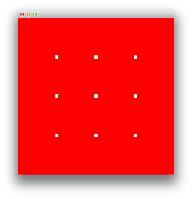
If we want to draw points instead of triangles from the above vertices, we need to change line 5 from display to:
1 glDrawArrays(GL_POINTS, 0, 12);We also need to enable GL_PROGRAM_POINT_SIZE in the initialize function:
1 glEnable(GL_PROGRAM_POINT_SIZE);With the above changes we can control the point size in pixels in the vertex shader with:
1 gl_PointSize = 10.0;The default point size in OpenGL is 1.0. With a point size of 10px, this is what you should see (ex_5.cpp from the Github repository):
What do you expect to see if you change GL_POINTS to GL_LINES ?
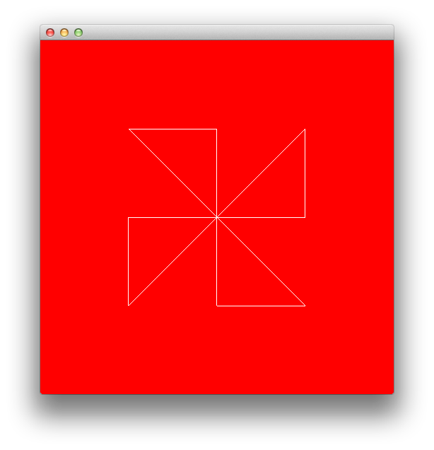
By default, OpenGL fills a triangle with color, it is however possible to change this behavior if we use the function glPolygonMode. Copy ex_4 to ex_6 and add this line at the end of the initialize function:
1 glPolygonMode(GL_FRONT_AND_BACK, GL_LINE);Now, OpenGL will draw for us a wireframe triangle:
It’s time to add some color to our triangles. Suppose that we have a color associated with each vertex from our image and that we’ve generated somehow these colors; we are going to need 12 RGB colors. How can we send them to the fragment shader ? If we look again at our simplified scheme of the OpenGL pipeline, we see that the data goes first through the vertex shader. This means that we need to add our 12 colors to the VBO and include a new input variable, for colors, in the vertex shader. After the color data is in the vertex shader, we are going to need to pass it through for the next stages of the pipeline toward the fragment shader, we will use an out variable for this:
 1 #version 150
 2
 3 in vec4 position;
 4 in vec4 color;
 5 out vec4 color_from_vshader;
 6
 7 void main() {
 8 	gl_Position = position;
 9 	color_from_vshader = color;
10 }
Similarly, the fragment shader needs to have an in variable (be sure to use the same name here as the name of the output from the vertex shader):
1 #version 150
2
3 in vec4 color_from_vshader;
4 out vec4 out_color;
5
6 void main() {
7 	out_color = color_from_vshader;
8 }
The out_color variable is implicitly bound to the output color from the fragment shader.
Back to the C++ code now, we are going to need a new array for the color data, technically we could store the color data in the same array as the vertex positions. Using a different array, will let as try a new technique for transferring data to the VBO. Suppose the color data is stored in an array named colors.
First, we need to allocate enough space for the VBO to store both the positions and the colors:
1 	glBindBuffer(GL_ARRAY_BUFFER, vbo);
2 	glBufferData(GL_ARRAY_BUFFER, sizeof(vertices_position) + sizeof(colors), NULL, GL_STATIC_DRAW);
We could use glBufferSubData to transfer vertices_position and colors to the VBO:
1 	// Transfer the vertex positions:
2 	glBufferSubData(GL_ARRAY_BUFFER, 0, sizeof(vertices_position), vertices_position);
3
4 	// Transfer the vertex colors:
5 	glBufferSubData(GL_ARRAY_BUFFER, sizeof(vertices_position), sizeof(colors), colors);
The second argument of glBufferSubData is the offset at which the data is located, because we put the position data first in the VBO, the offset is 0. When we need to put the color data, the offset is equal to the size of the data that is already in the VBO sizeof(vertices_positons) in our case. The third parameter is the size of the data transferred and the fourth parameter a pointer to the data.
Now, we need to add a new attribute, the color attribute, that enters the vertex shader:
1 	// Color attribute
2 	GLint color_attribute = glGetAttribLocation(shaderProgram, "color");
3 	glVertexAttribPointer(color_attribute, 3, GL_FLOAT, GL_FALSE, 0, (GLvoid *)sizeof(vertices_position));
4 	glEnableVertexAttribArray(color_attribute);
The last argument from glVertexAttribPointer is a pointer to where the first element of the attribute is located.
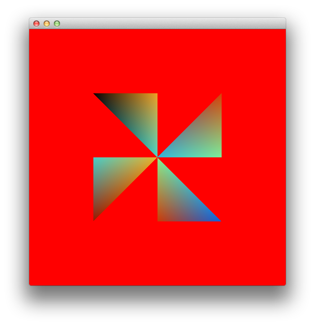
For a more interesting effect, we can fill colors with random numbers from 0 to 1:
 1 	GLfloat colors[36];
 2
 3 	// Initialize the random seed from the system time
 4 	srand(time(NULL));
 5
 6 	// Fill colors with random numbers from 0 to 1, use continuous polynomials for r,g,b:
 7 	int k = 0;
 8 	for(int i = 0; i < sizeof(colors)/sizeof(float)/3; ++i) {
 9 		float t = (float)rand()/(float)RAND_MAX;
10 		colors[k] = 9*(1-t)*t*t*t;
11 		k++;
12 		colors[k] = 15*(1-t)*(1-t)*t*t;
13 		k++;
14 		colors[k] = 8.5*(1-t)*(1-t)*(1-t)*t;
15 		k++;
16
17 	}
The complete code for the last exercise can be found on the Github repository for this article as ex_7.
If you run the code, you should see an image similar with this one:
Suppose now that we want to draw a square with the lower left corner at -0.5, -0.5 and the upper right corner at 0.5, 0.5. We can draw a square as a reunion of two triangular surfaces, basically we could use a strategy similar with the one we’ve used earlier, except that in this case we are going to have six vertices instead of twelve:
 1 	// 1 square (made by 2 triangles) to be rendered
 2 	GLfloat vertices_position[12] = {
 3 		-0.5, -0.5,
 4 		0.5, -0.5,
 5 		0.5, 0.5,
 6
 7 		0.5, 0.5,
 8 		-0.5, 0.5,
 9 		-0.5, -0.5
10 	};
In this case, the colors array will have 18 elements. Another change that should be made is in the display function, glDrawArrays should draw now 6 vertices. You can see the complete code as ex_8.cpp on Github.
If you run the code, you will see an image similar with this one:
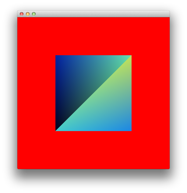
First thing that we should notice from the above image, is that the color is not smoothly distributed on the square surface, this is because the vertices -0.5, -0.5 and 0.5, 0.5 are repeated in our list of vertices and have different colors (see the way the color list is randomly generated).
Please note that we use sizeof(GLfloat)∗12 bytes for storing the vertices and sizeof(GLfloat)∗18 to store the colors, this means that we need 120 bytes to store the data for drawing a square.
A better way to represent our data will be to store the triangles as an array of indices pointing to an array of vertices, basically we will have one index per vertex:
 1 	// 1 square (made by 2 triangles) to be rendered
 2 	GLfloat vertices_position[8] = {
 3 		-0.5, -0.5,
 4 		0.5, -0.5,
 5 		0.5, 0.5,
 6 		-0.5, 0.5,
 7 	};
 8
 9 	GLuint indices[6] = {
10 		0, 1, 2,
11 		2, 3, 0
12 	};
13
14 	GLfloat colors[12];
15
16 	...
In this case, the array of vertices will have unique entries, no vertices is repeated, this will also result in a reduction in the memory used to store the data for drawing a square. The memory consumption is now sizeof(GLfloat)∗8 for the vertices, sizeof(GLuint)∗6 for the indices and sizeof(GLfloat)∗12 for the colors, on my machine this is 104 bytes. This may not sound like much for this particular case, but for a complex 3D scene the reduction in the memory consumption can be significative. Take as example a 3D cube, we have 6 faces and 8 vertices, using the first method our list of vertices will need to have 36 entries (in this case the memory consumption will be even larger because we’ll need to explicitly store 3 coordinates for each vertex), while with the second, more effective method, the list of vertices will have only 8 entries.
The next figure exemplifies better how we can get the position for a square corner using the indices and the vertices_position arrays:
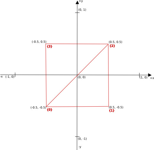
How do we get the position for a particular triangle ? First we go in the indices array and we get the indices, for example the second triangle will have as indices 2, 3, 0. The second step is to go in the vertices_position array and get the actual position, for index = 3 we’ll have x = 0.5 and y = 0.5.
Fortunately for us, OpenGL already has a special command for drawing data stored as arrays of indices and vertices, glDrawElements, and a special type of buffer data for storing the indices array, GL_ELEMENT_ARRAY_BUFFER.
We’ll need to create an Element Array Buffer, bind it, allocate space and transfer the indices array to this buffer:
1 	// Create an Element Array Buffer that will store the indices array:
2 	GLuint eab;
3 	glGenBuffers(1, &eab);
4
5 	// Transfer the data from indices to eab
6 	glBindBuffer(GL_ELEMENT_ARRAY_BUFFER, eab);
7 	glBufferData(GL_ELEMENT_ARRAY_BUFFER, sizeof(indices), indices, GL_STATIC_DRAW);
And the draw command is now:
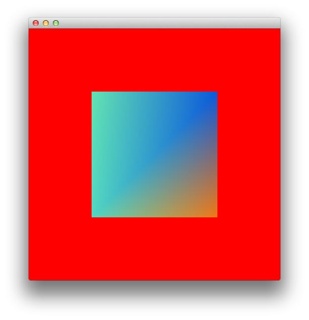
1 glDrawElements( GL_TRIANGLES, 6, GL_UNSIGNED_INT, 0);The complete code for this example is on the Github repository for this article as ex_9.cpp.
If you run the code, you should see an image similar with this one:
In the next tutorial, we are going to learn how to work with textures in OpenGL and how to load an image from the disk, with FreeImage.
All posts from this series:
- OpenGL 101: Windows, OS X and Linux - Getting Started
- OpenGL 101: Drawing primitives - points, lines and triangles
- OpenGL 101: Textures
- OpenGL 101: Matrices - projection, view, model
If you are interested to learn more about OpenGL, I would recommend reading OpenGL SuperBible by G. Sellers, S Wright and N. Haemel:

or
OpenGL Programming Guide by D. Shreiner, G. Sellers, J. M. Kessenich, B. M. Licea-Kane: