Raspberry Pi - Using C++ to control a group of LEDs
Posted on December 23, 2018 by Paul
In this article, I will show you how to use C++ to control a group of LEDs connected to a Raspberry Pi. You can see the final results in this short video:
List of components:
- 1 Raspberry Pi (any recent version should work);
- 1 Breadboard;
- 3 LEDs;
- 3 220 Ω resistors;
- 4 jump wires.
Note: In my setting I’ve used a T cobbler to connect the Raspberry Pi GPIO pins to a small breadboard, this has the advantage that I can easily see the named pins of the Pi. However, you can also directly connect the RPi pins to your main breadboard using a couple of female-male Dupont wires.
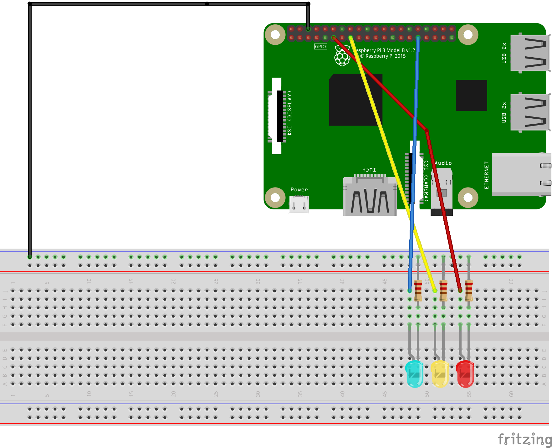
I’ve connected the positive leg, the anode, of each of the three LEDs to one of the Pi’s pins in this order: 17, 22 and 6. If you want to see your Pi pins layout, use this command in a Terminal on your RPi:
1 pinoutThe negative leg, the cathode, of each LED is connected to the ground rail of my breadboard using a 220 Ω resistor. Also, I’ve used a jump wire to connect the ground rail of the breadboard to one of the RPi’s ground pins.
In the next diagram, made with Fritzing, you can see a more clear picture of how the circuit was wired:
You should have an up to date version of Raspbian installed on your RPi. In my case, I’ve used the latest available version of Raspbian Stretch with desktop and recommended software. The advantage of using the full Raspbian version is that you have everything included: a C++ compiler and the wiringPi library used to access the GPIO pins. If you are using Raspbian Lite, you will probably need to use the apt package manager to install GCC and wiringPi.
Assuming that you’ve finished assembling the above circuit, we can write the C++ code that we’ll use to control the three LEDs. I’ve saved the next code in a file named led_control.cpp:
 1 #include <iostream>
 2 #include <wiringPi.h>
 3 #include <csignal>
 4
 5 // global flag used to exit from the main loop
 6 bool RUNNING = true;
 7
 8 // Blink an LED
 9 void blink_led(int led, int time) {
10     digitalWrite(led, HIGH);
11     delay(time);
12     digitalWrite(led, LOW);
13     delay(time);
14 }
15
16 // Callback handler if CTRL-C signal is detected
17 void my_handler(int s) {
18     std::cout << "Detected CTRL-C signal no. " << s << '\n';
19     RUNNING = false;
20 }
21
22 int main() {
23     // Register a callback function to be called if the user presses CTRL-C
24     std::signal(SIGINT, my_handler);
25
26     // Initialize wiringPi and allow the use of BCM pin numbering
27     wiringPiSetupGpio();
28
29     std::cout << "Controlling the GPIO pins with wiringPi\n";
30
31     // Define the 3 pins we are going to use
32     int red = 17, yellow = 22, green = 6;
33
34     // Setup the pins
35     pinMode(red, OUTPUT);
36     pinMode(yellow, OUTPUT);
37     pinMode(green, OUTPUT);
38
39     int time = 1000;   // interval at which a pin is turned HIGH/LOW
40     while(RUNNING) {
41         blink_led(red, time);
42         blink_led(yellow, time);
43         blink_led(green, time);
44     }
45
46     std::cout << "Program ended ...\n";
47 }
You can compile and run the code with:
1 g++ led_control.cpp -o led_control
2 ./led_control
The above code starts by registering a callback handler that will be called if the user presses CTRL-C, this is useful to do a clean exit from the program main loop.
Next, we initialize the wiringPi library using wiringPiSetupGpio. This function will let us use the BCM pin numbering layout, which is the numbering system you will find in the official Raspberry Pi GPIO documentation. As a side note, for historical reasons, wiringPi uses his own numbering layout.
If you are curious to see the difference between the BCM numbering layout and wiringPi, use the next command in a Terminal:
1 gpio readallThis is what I see on my machine:
 1 pi@raspberrypi:~ $ gpio readall
 2  +-----+-----+---------+------+---+---Pi 3---+---+------+---------+-----+-----+
 3  | BCM | wPi |   Name  | Mode | V | Physical | V | Mode | Name    | wPi | BCM |
 4  +-----+-----+---------+------+---+----++----+---+------+---------+-----+-----+
 5  |     |     |    3.3v |      |   |  1 || 2  |   |      | 5v      |     |     |
 6  |   2 |   8 |   SDA.1 |   IN | 1 |  3 || 4  |   |      | 5v      |     |     |
 7  |   3 |   9 |   SCL.1 |   IN | 1 |  5 || 6  |   |      | 0v      |     |     |
 8  |   4 |   7 | GPIO. 7 |   IN | 1 |  7 || 8  | 0 | IN   | TxD     | 15  | 14  |
 9  |     |     |      0v |      |   |  9 || 10 | 1 | IN   | RxD     | 16  | 15  |
10  |  17 |   0 | GPIO. 0 |   IN | 0 | 11 || 12 | 0 | IN   | GPIO. 1 | 1   | 18  |
11  |  27 |   2 | GPIO. 2 |   IN | 0 | 13 || 14 |   |      | 0v      |     |     |
12  |  22 |   3 | GPIO. 3 |   IN | 0 | 15 || 16 | 0 | IN   | GPIO. 4 | 4   | 23  |
13  |     |     |    3.3v |      |   | 17 || 18 | 0 | IN   | GPIO. 5 | 5   | 24  |
14  |  10 |  12 |    MOSI | ALT0 | 0 | 19 || 20 |   |      | 0v      |     |     |
15  |   9 |  13 |    MISO | ALT0 | 0 | 21 || 22 | 0 | IN   | GPIO. 6 | 6   | 25  |
16  |  11 |  14 |    SCLK | ALT0 | 0 | 23 || 24 | 1 | OUT  | CE0     | 10  | 8   |
17  |     |     |      0v |      |   | 25 || 26 | 1 | OUT  | CE1     | 11  | 7   |
18  |   0 |  30 |   SDA.0 |   IN | 1 | 27 || 28 | 1 | IN   | SCL.0   | 31  | 1   |
19  |   5 |  21 | GPIO.21 |   IN | 1 | 29 || 30 |   |      | 0v      |     |     |
20  |   6 |  22 | GPIO.22 |   IN | 1 | 31 || 32 | 0 | IN   | GPIO.26 | 26  | 12  |
21  |  13 |  23 | GPIO.23 |   IN | 0 | 33 || 34 |   |      | 0v      |     |     |
22  |  19 |  24 | GPIO.24 |   IN | 0 | 35 || 36 | 0 | IN   | GPIO.27 | 27  | 16  |
23  |  26 |  25 | GPIO.25 |   IN | 0 | 37 || 38 | 0 | IN   | GPIO.28 | 28  | 20  |
24  |     |     |      0v |      |   | 39 || 40 | 0 | IN   | GPIO.29 | 29  | 21  |
25  +-----+-----+---------+------+---+----++----+---+------+---------+-----+-----+
26  | BCM | wPi |   Name  | Mode | V | Physical | V | Mode | Name    | wPi | BCM |
27  +-----+-----+---------+------+---+---Pi 3---+---+------+---------+-----+-----+
28 pi@raspberrypi:~ $
Next, we define the three pins we are going to use and set them as output pins.
Finally, we start the main loop of the program, this will run as long as the global flag RUNNING is true. Inside the main loop, we use the blink_led function to start an LED, wait one second, stop the LED, wait one second, start the next LED and so …
Please note how we are using the RUNNING variable to do a clean program exit. When the user presses CTRL-C the my_handler function is called which will set the RUNNING variable to false. Otherwise, without catching the SIGINT signal (which is triggered by CTRL-C), if you simply stop the program using CTRL-C you can, potentially, leave one of the output pins on and you will end up with some LED always on.
If you want to learn more about programming on the Raspberry Pi, a very good book is Exploring Raspberry Pi by Derek Molloy:

If you are interested to learn more about modern C++, I recommend A Tour of C++ by Bjarne Stroustroup: